Building a 4-in-1 Montessori Learning Tower
I built this 4-in-1 Montessori learning tower for my daughter using mostly leftover MDF, wood, and filament from previous projects.
The design is based on the HM0001 learning tower from Só Berços:
Original product page — Só Berços
What interested me about this model was the way it changes function without folding. Upright, it works as a learning tower. When the whole structure is placed on its side, it becomes a small table and chair.
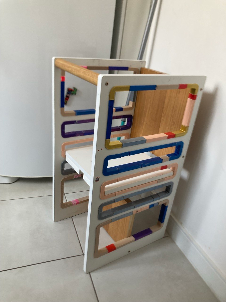
I did not have the original woodworking drawings, so the first part of the project was figuring out how the original was built.
Reverse engineering the original design
The product page provided the external dimensions:
- 780 mm high;
- 344 mm wide;
- 430 mm deep.
The manufacturer also provides an assembly manual.
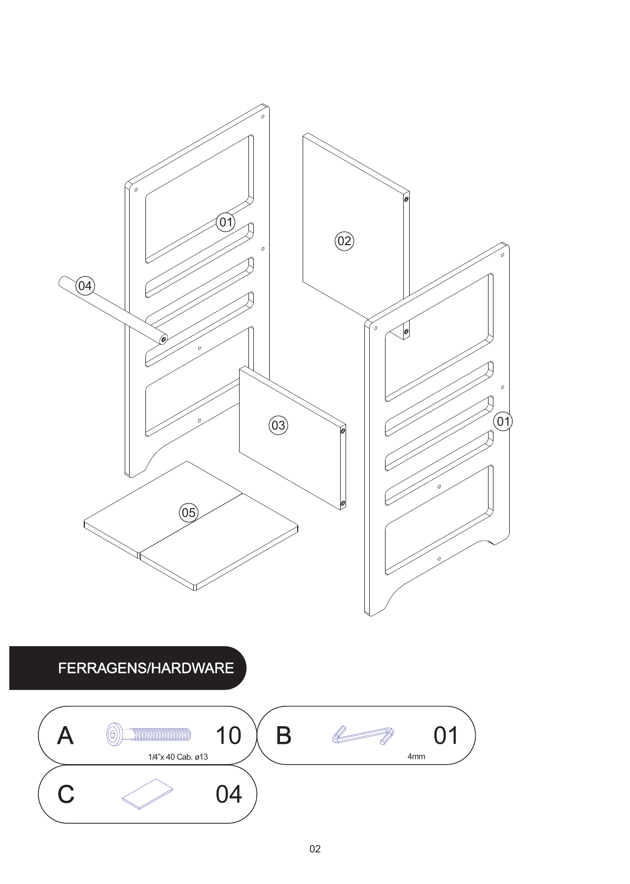
The manual shows the main structure clearly:
- two identical side panels;
- two fixed internal panels;
- one wooden upper bar;
- one removable platform.
What it does not provide is a complete set of dimensions for all those parts.
I used ChatGPT to help reconstruct the missing measurements from the manual and the known external dimensions.
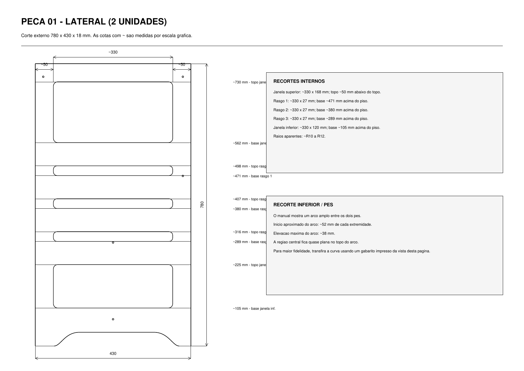
We used the 780 × 430 mm side panel as the main reference, rectified the drawings from the manual, and estimated the positions and sizes of the openings.
One of the drawings we created during that process looked like this:
We also reconstructed the other parts:
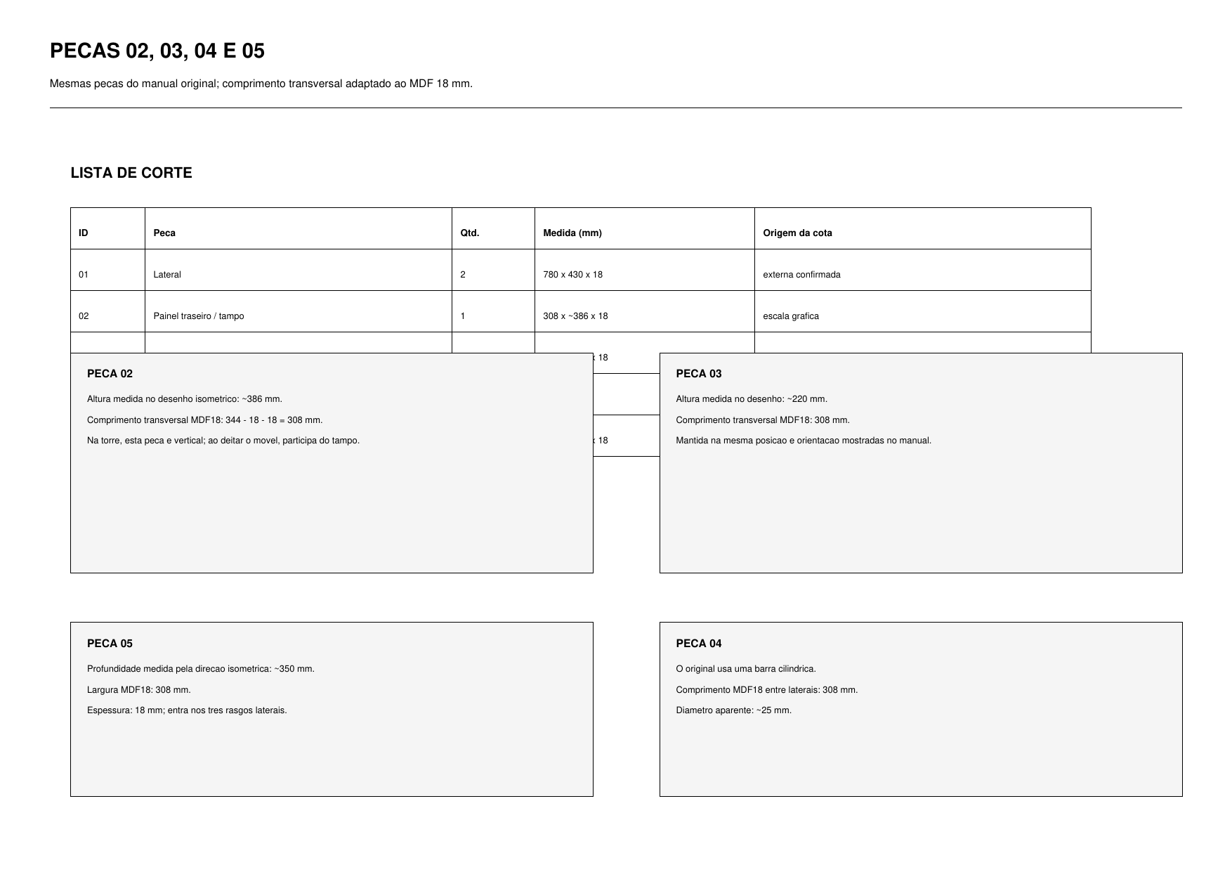
And later combined the measurements into a more complete technical drawing:
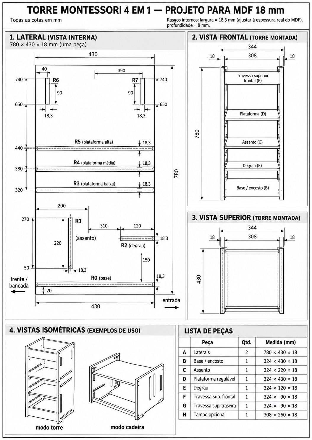
The external measurements came from the original product. The internal measurements were calculated from the drawings published here, so they are only approximations.
I used 18 mm MDF for the side panels.
Materials
I did not buy all the material specifically for this project.
The white side panels are MDF.
The brown pieces are leftover wood I already had, and they are thicker than the MDF.
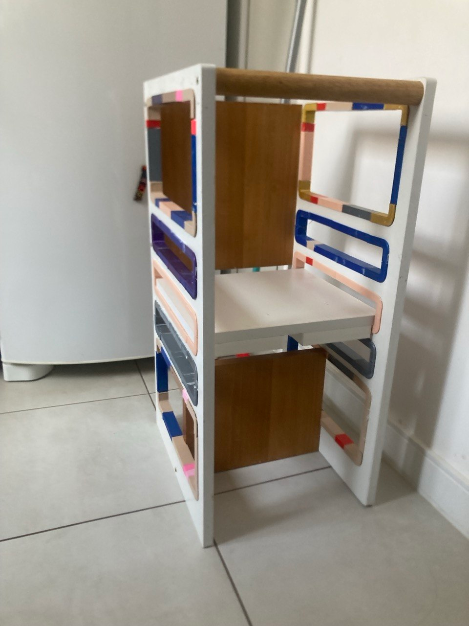
Those brown pieces became the fixed internal panels.
When the tower is upright, they stay vertical. When the tower is placed on its side, one becomes the tabletop and the other becomes the seat.
Cutting the side panels
The side panels were the most complicated parts because of the large internal openings and the rounded corners.
I cut the openings roughly with a jigsaw and then used the router to clean the edges and shape the inner corners.
That part did not go as planned.
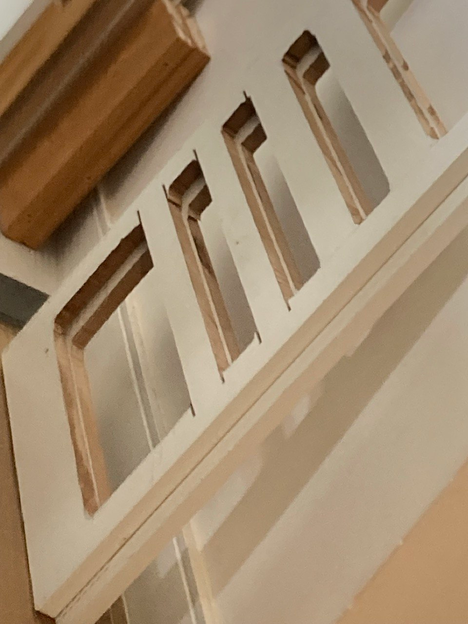
Some corners came out rough, some MDF edges chipped, and in a few places I removed more material than I wanted.
The openings were still usable, so I kept the panels. The problem was mainly the finish around the internal edges.
Fixing the internal cuts
The 3D-printed borders were not part of the original plan.
I made them after the problem with the internal cuts as an alternative to rebuilding the side panels.
We first generated a curved piece to follow the opening. I then cut that curve down and made another model from it.
The two STLs below show that process, and both were part of what I printed to get to the final colorful border.
First, the base curve:
Then, the derived STL:
I had several small amounts of leftover filament, so I printed the pieces in the colors I had available.
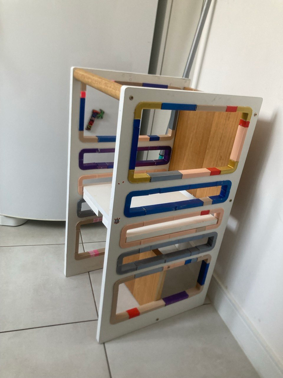
The printed pieces cover the rough MDF edges and create a consistent border around the openings.
Adjustable platform
The removable platform fits into different horizontal openings in the side panels.
This allows the platform height to be changed without modifying the structure.
The wooden bar at the top connects the two side panels and closes the open side of the tower.
Table and chair mode
This is the part of the original design that made me choose this model.
The tower does not fold.
You place the whole structure on its side.
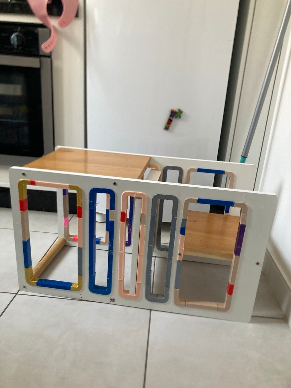
The two brown internal panels change orientation with the rest of the structure.
One becomes the tabletop.
The other becomes the seat.
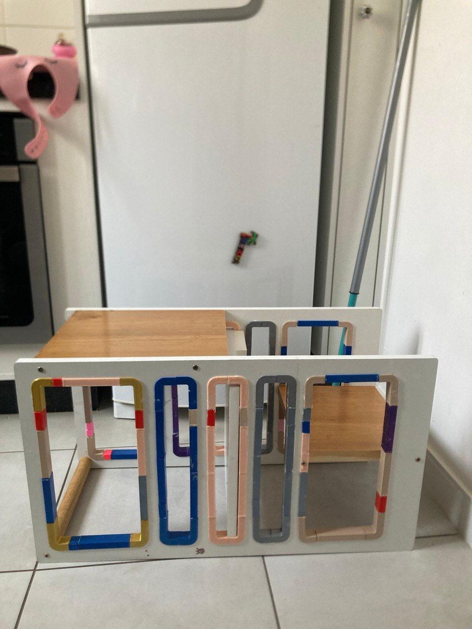
The side panels remain the main structure in both positions.
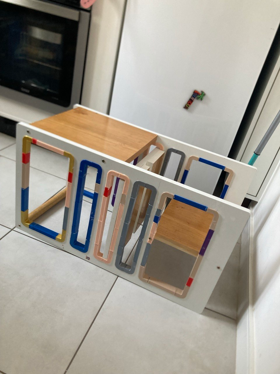
The same pieces are used in both configurations.
What I would change next time
If I built another one, I would change the way I make the internal openings.
I would make proper router templates before cutting the final side panels.
I would also leave more material during the jigsaw cut and use a flush-trim bit against the template to establish the final shape.
The main problem in this build was trying to control the final geometry of those openings without a proper template.
The printed borders solved that problem on this one.
Result
The tower is finished and in use.
My daughter uses it at the kitchen counter and also in the table-and-chair position.
The project ended up combining reverse engineering, MDF work, leftover wood, routing, and 3D printing.
This article documents my build and reverse-engineering process. This is not an official drawing and it is not guaranteed by any safety standard.